


Description
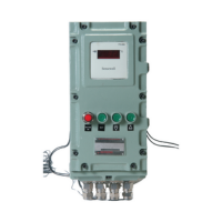
How Does an FLP Annunciator Work?
Key Components
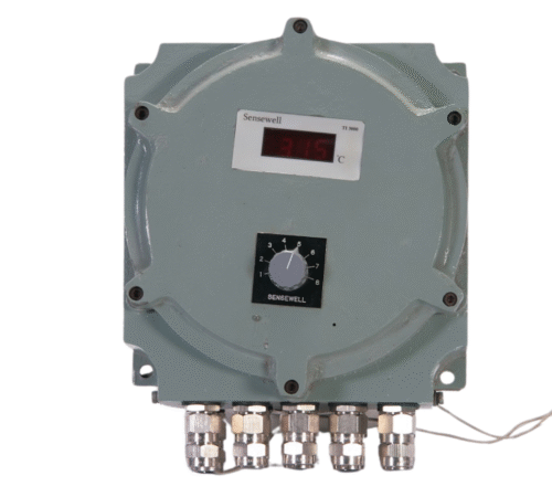
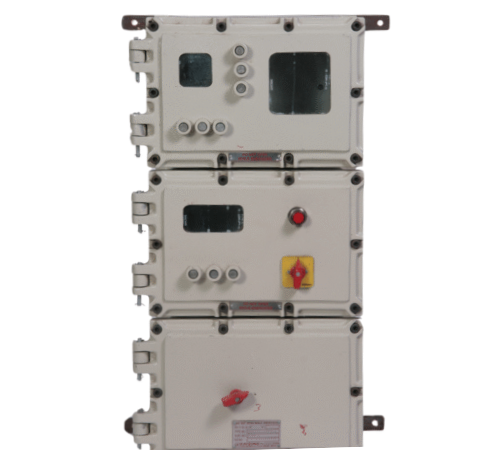
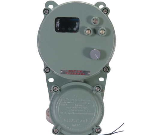
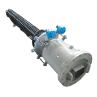
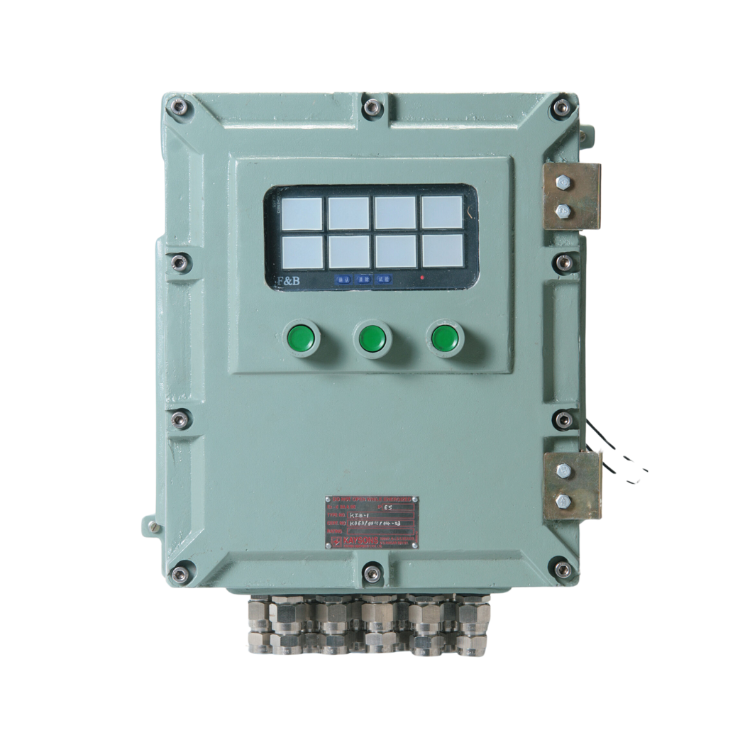
1. Flameproof Enclosure: Made from materials like aluminum LM-6 or stainless steel,
certified for hazardous areas with ingress protection ratings like IP65 or IP66.
2. Input Channels: Accepts multiple inputs (e.g., 4–48 channels) from sensors, switches, or
control systems to monitor parameters like temperature, pressure, or flow.
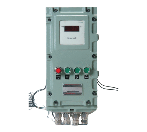
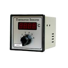
3. Display Panel: Features LED indicators, lamps, or LCD screens to show alarm status for
each channel, often with color-coded alerts (e.g., red for critical, amber for warning).
4. Audible Alarms: Built-in buzzers or hooters provide loud alerts (e.g., 80–100 dB) to
ensure operator attention in noisy environments.
5. Microcontroller: Processes input signals, triggers alarms based on programmed logic,
and supports features like alarm acknowledgment or test modes.
6. Communication Interfaces: Optional RS485 Modbus, RS232, or relay outputs for
integration with SCADA, PLC, or DCS systems.
7. Power Supply: Typically operates on 230 V AC, 110 V AC, or 24 V DC, with low
power consumption for reliability.
Working Principle
Input Monitoring: The annunciator receives signals from sensors or control systems
monitoring process parameters (e.g., high temperature, low pressure).
Alarm Activation: When a parameter exceeds programmed thresholds, the
microcontroller triggers visual (LED/lamp) and audible (buzzer) alarms for the
corresponding channel.
Display: The panel indicates the alarm status, often with channel-specific indicators and
a common alarm output.
Operator Response: Operators can acknowledge alarms using push buttons, silencing
the audible alert while the visual indicator remains active until the fault is resolved.
Safety: The flameproof enclosure ensures safe operation in hazardous areas (Zone 1 or
Zone 2), preventing ignition of flammable gases or dust.
Data Integration: Optional communication interfaces allow alarm data to be logged or
transmitted to control systems for further analysis.